Aurelia X4 UAV: Full-Stack Drone Autonomy
Led a team of five to build a complete ROS 2 control system for the Aurelia X4 heavy-lift quadcopter. Full sim-to-real pipeline spanning URDF modeling, Gazebo Fortress simulation, ArduPilot SITL, MAVROS flight control, and ArUco-based precision landing with a Sony RX0 II camera. FAA-certified Remote PIC. First team to deliver a working implementation after multiple prior cohorts failed.
Aurelia X4 UAV: Full-Stack Drone Autonomy
Overview
Led a team of five to build a complete ROS 2 control system for the Aurelia X4 heavy-lift quadcopter. Full sim-to-real pipeline spanning URDF modeling, Gazebo Fortress simulation, ArduPilot SITL, MAVROS flight control, and ArUco-based precision landing with a Sony RX0 II camera. FAA-certified Remote PIC. First team to deliver a working implementation after multiple prior cohorts failed.
Overview
This was my capstone project for Robot System Programming at Johns Hopkins, and it’s the one I’m proudest of from grad school. I served as team lead, FAA-certified Remote Pilot-in-Command, and principal software architect for a team of five building a complete ROS 2 autonomy stack for the Aurelia X4, a professional heavy-lift quadcopter with a CubePilot Cube Orange flight controller running ArduPilot.
What made this project meaningful is the context: multiple previous student cohorts had attempted this same platform and failed to get a working system. The drone had hardware issues from prior semesters, the software stack was fragmented, and nobody had managed to close the loop from simulation to real flight. On top of that, the Aurelia X4 had zero existing ROS or ROS 2 support. No URDF, no Gazebo plugins, no community packages, nothing. Every other popular drone platform (Iris, Crazyflie, Tello) has ready-made ROS integrations you can pull off the shelf. We had to build ours from scratch.
That meant starting from the mechanical specifications and working through the physics ourselves. We measured the airframe dimensions, weighed individual components, and computed inertia tensors for each link to build an accurate URDF/xacro model. Getting the Gazebo simulation to match the real drone’s behavior required tuning motor thrust curves, drag coefficients, and mass distributions so the simulated flight controller would produce responses that transferred to the physical aircraft. If the sim model is wrong, the ArduPilot SITL tunes mean nothing on real hardware, so we treated the physics modeling as a first-class engineering task rather than an afterthought.
Our team diagnosed the hardware problems, rebuilt the software architecture from scratch in ROS 2 Humble, and delivered the first stable implementation. We flew the physical drone successfully, something no team before us had accomplished on this platform.
The system spans seven ROS 2 packages covering URDF modeling, Gazebo Fortress simulation, ArduPilot SITL integration, MAVROS flight control, ArUco-based precision landing with a Sony RX0 II camera, and a unified launch system that runs the same codebase in simulation and on real hardware.
Demo
Hardware
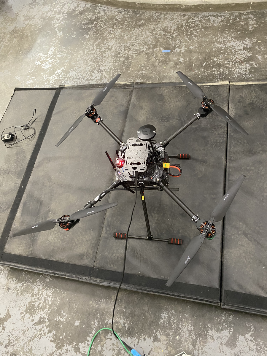
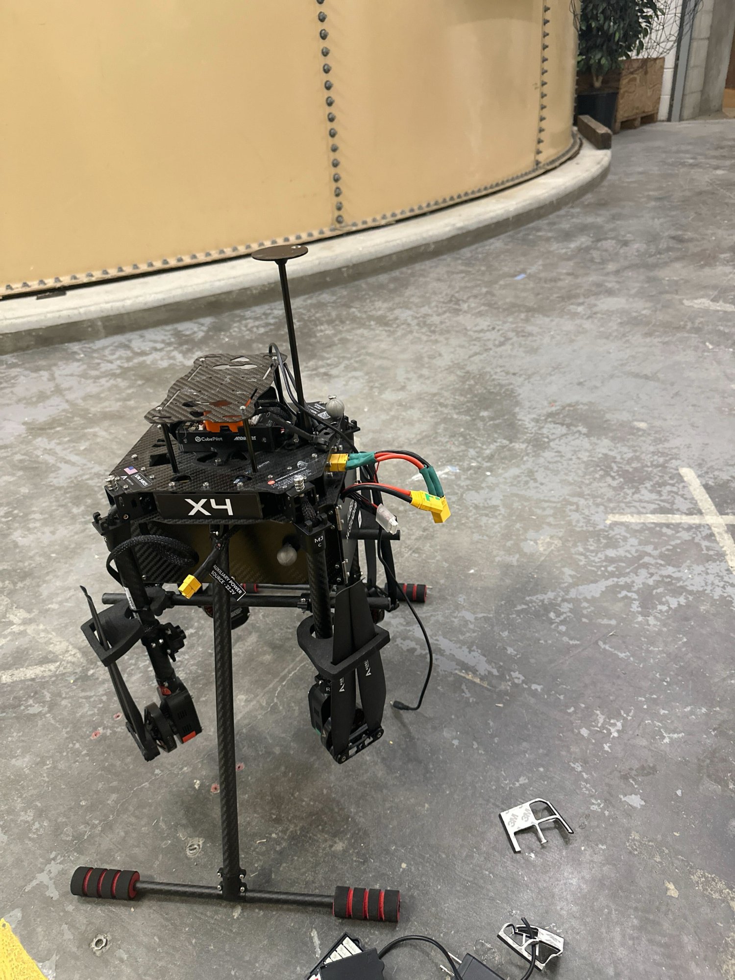
The Aurelia X4 with arms folded during a bench test session at JHU. Visible: CubePilot Cube Orange flight controller, GPS mast, XT60 power connectors, and carbon fiber frame.
Motor arm spin-up test validating motor direction, ESC calibration, and propeller configuration before first flight.
Left: RViz visualization showing the X4 URDF model with TF frames for all four propellers, camera, IMU, and drone body. Right: MAVROS terminal output showing the full arming sequence, including GUIDED mode switch, motor arm confirmation, and ROS 2 service calls.
Simulation
This is the Gazebo Fortress SITL takeoff running the full pipeline: x4_bringup launches the Gazebo world with our custom URDF model, spins up ArduPilot SITL, connects MAVROS, and then executes the takeoff service script. The drone you see lifting off is using the same flight controller code, the same MAVROS interface, and the same ROS 2 service calls that run on the physical Cube Orange. The only difference is the use_sim:=true flag in the launch file. More simulation recordings (waypoint navigation, loiter, landing sequences) will be added later this week.
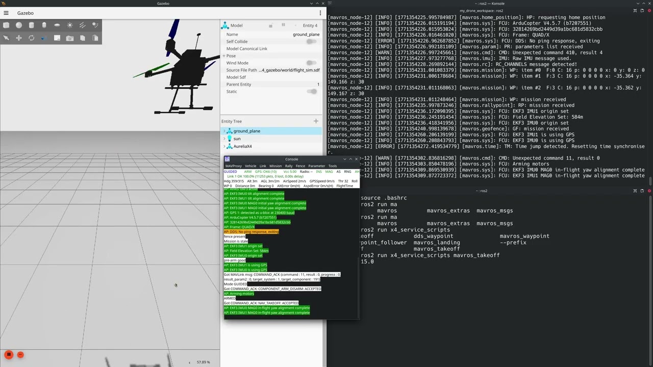
Click to watch: Gazebo Fortress SITL takeoff. ArduPilot SITL running the same flight controller firmware as the physical Cube Orange, commanded through MAVROS service calls via ROS 2.
System Architecture
flowchart TB
    subgraph Launch["x4_bringup"]
        A["x4_startup.launch.py"]
    end

    subgraph Sim["Simulation Stack"]
        B["Gazebo Fortress"]
        C["ArduPilot SITL"]
    end

    subgraph Hardware["Real Hardware"]
        D["CubePilot Cube Orange"]
        E["Aurelia X4"]
    end

    subgraph ROS2["ROS 2 Humble"]
        F["MAVROS Bridge"]
        G["x4_service_scripts"]
        H["x4_vision"]
        I["x4_description"]
    end

    A -->|"use_sim:=true"| B
    A -->|"use_real:=true"| D
    B <-->|"MAVLink"| C
    D <-->|"MAVLink"| E
    C <-->|"MAVLink"| F
    D <-->|"MAVLink"| F
    F --> G
    G -->|"Arm / Takeoff / Waypoints"| F
    H -->|"ArUco Pose"| G
    I -->|"URDF + Meshes"| B
Why This Project Matters
The History
The Aurelia X4 had been assigned to student teams in prior semesters. Despite significant effort, none of them managed to deliver a working system. The hardware had accumulated damage from previous attempts, the software was a patchwork of incomplete packages, and there was no clear path from simulation to real flight. When our team inherited the project, we essentially started from a broken drone and an empty ROS 2 workspace.
What We Did Differently
Rather than trying to patch what existed, we made the decision to rebuild from the ground up. I structured the project around seven cleanly separated ROS 2 packages, each with a single responsibility:
x4_description contains the URDF/xacro model we built from scratch by working through the Aurelia X4’s mechanical specifications. Since no existing model existed anywhere, we measured the physical airframe, weighed each structural component and actuator, and derived the inertia matrices by hand. The model includes mesh files for visualization, collision geometries for Gazebo’s physics engine, and sensor frames for the GPS, IMU, and camera. This package is shared between simulation and real hardware, so everything that follows is built on the same geometric truth.
Platform Specifications
We pulled these from the Aurelia Aerospace datasheets and validated them against our physical unit:
| Parameter | Value |
|---|---|
| Empty weight | 2,450 g (5.40 lb) |
| MTOW (LiPo / LE) | 5,212 g / 5,424 g |
| Max payload | 1.5 kg (3.3 lb) |
| Max speed | 56 km/h (35 mph) |
| Max wind resistance | 32 km/h (20 mph) |
| Max service ceiling | 3,000 m ASL |
| Flight time (standard / LE) | 25 min / 40 min |
| Flight range | Up to 5 km |
| Battery | 6S 22.2V LiPo (10,000 mAh) |
| Flight controller | CubePilot Cube Orange with ADS-B |
| GPS | uBlox M9N (GPS, GLONASS, Galileo, BeiDou) |
| Compass | RM3100 |
| IMU redundancy | 2 accelerometers, 2 gyroscopes, 1 magnetometer |
| Rangefinder | LiDAR, 0-12 m range, $\pm$6 cm accuracy |
| Airframe span | 835 mm |
| Software | ArduPilot Copter 4.5 |
SolidWorks Mass Properties for URDF
To get the Gazebo simulation right, we needed accurate mass and inertia properties for every link in the URDF. I used SolidWorks to compute the mass properties from the provided CAD model, making minor adjustments to account for the top box and landing gear which were not included in the original geometry.
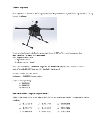
The full inertia tensor at the center of mass, aligned with the output coordinate system and using positive tensor notation:
\[\mathbf{I}_{\text{CoM}} \;=\; \begin{bmatrix} I_{xx} & I_{xy} & I_{xz} \\ I_{yx} & I_{yy} & I_{yz} \\ I_{zx} & I_{zy} & I_{zz} \end{bmatrix} \;=\; \begin{bmatrix} 0.1548 & 0.0026 & -0.0000 \\ 0.0026 & 0.1863 & 0.0035 \\ -0.0000 & 0.0035 & 0.1628 \end{bmatrix} \;\text{kg}\!\cdot\!\text{m}^2\]The near-zero off-diagonal terms ($I_{xz}$, $I_{zx}$) confirm the airframe’s bilateral symmetry about the $xz$-plane, which is expected for a quad-X configuration. The center of mass sits almost exactly at the geometric center:
\[\mathbf{r}_{\text{CoM}} \;=\; \begin{bmatrix} -0.031 \\ -0.728 \\ -6.885 \end{bmatrix} \;\text{mm}\]The total mass at MTOW came out to $m = 5.424\;\text{kg}$, matching the Aurelia LE specification. These values were plugged directly into the URDF’s <inertial> tags, and getting them right was critical. If the inertia tensor is even moderately wrong, the ArduPilot SITL PID tuning will not transfer to hardware, and the drone either oscillates or drifts on real flights.
x4_gazebo handles the Ignition Gazebo Fortress simulation environment, including world files, plugin configurations, and simulation-specific launch files. We used the ArduPilot Gazebo plugin to connect the simulated airframe to ArduPilot’s SITL (Software in the Loop), which means the flight controller running in simulation is identical to the one running on the physical Cube Orange. The simulation takeoff video above is this package in action: the Gazebo world loads our custom URDF, the ArduPilot plugin bridges the simulated sensors and actuators, and the MAVROS takeoff service sends the same commands that would go to real hardware.
x4_bringup is the entry point. A single launch file brings up the entire system with a use_sim or use_real flag, which means the same ROS 2 graph runs in both contexts. This sim-to-real parity was a deliberate design choice, and it’s what let us iterate quickly in Gazebo before committing to real flights.
x4_service_scripts wraps common flight operations (takeoff, landing, waypoint navigation, loiter) into simple ROS 2 service calls through MAVROS. Instead of manually issuing MAVLink commands, a teammate or test script can just run ros2 run x4_service_scripts mavros_takeoff alt:=10.0.
x4_vision streams video from the Sony RX0 II camera, detects ArUco markers using OpenCV, and publishes 6DOF pose estimates for downstream precision landing logic. The pipeline loads camera intrinsics from calibration, runs marker detection in real time, and estimates the marker’s position and orientation relative to the drone.
x4_interfaces defines custom ROS 2 message and service types for communication between packages.
x4_moveit provides a high-level MoveIt 2 integration for flight planning, using a floating virtual joint to represent the drone’s 6DOF freedom in the workspace.
Flight Control via MAVROS
We chose MAVROS over ArduPilot’s native DDS interface (Micro-XRCE-DDS) because at the time of development, DDS support in ArduPilot Copter 4.5 was limited to only mode switching and arming. MAVROS gave us access to the full MAVLink command set, including takeoff, landing, waypoint navigation, and velocity commands, all exposed as standard ROS 2 services and topics.
The flight control pipeline works as follows. A service script sends a SetMode request to switch the vehicle to GUIDED mode. Then an arming command enables the motors. From there, the script can issue a CommandTOL (takeoff/land) or publish SET_POSITION_TARGET_LOCAL_NED messages for waypoint following. Each step includes response validation so the system confirms the vehicle has actually transitioned before moving to the next command.
For real hardware flights, the only change is the MAVROS fcu_url parameter, which switches from the SITL UDP endpoint to a serial connection to the physical Cube Orange. Everything else in the ROS 2 graph remains identical. You can see this exact pipeline executing in both the simulation takeoff video and the night flight video below: the same mavros_takeoff service script commanding the same GUIDED mode switch, arming sequence, and altitude command.
Vision-Based Precision Landing
The x4_vision package implements an ArUco marker detection pipeline for precision landing. The Sony RX0 II camera is mounted on the drone’s underside and streams frames over USB as a UVC device. The detection pipeline runs in three stages:
First, the raw frame is undistorted using camera intrinsics from a calibration file. Then OpenCV’s ArUco detector identifies markers from the DICT_4X4_50 dictionary in the corrected image. Finally, for each detected marker, estimatePoseSingleMarkers() computes the marker’s 6DOF pose (position and orientation) relative to the camera frame using the known marker size (15 cm) and the calibrated intrinsics.
The resulting pose is published as a PoseStamped message on /aruco/pose, which downstream nodes can use to command lateral corrections during the landing approach. The marker’s translation vector $\mathbf{t} = [t_x,\; t_y,\; t_z]^T$ gives the 3D offset from the camera to the marker center, and the rotation vector $\mathbf{r}$ (Rodrigues form) encodes the marker’s orientation. For landing, the key signals are $t_x$ and $t_y$ (lateral error to correct) and $t_z$ (altitude above the marker).
The Physical Flights
Getting from simulation to real flight involved more than just changing a launch parameter. I had to diagnose and repair hardware damage from previous semesters, recalibrate the Cube Orange’s sensors (accelerometer, compass, GPS), verify motor spin directions, and perform multiple ground tests before we were cleared for flight. As the FAA-certified Remote Pilot-in-Command (Part 107), I was responsible for all flight safety decisions, airspace compliance, and go/no-go calls.
We tested in both daylight and nighttime conditions. The nighttime flights were particularly important because they stress-tested our GPS lock stability and our ability to maintain situational awareness without visual line-of-sight cues.
The Crash
I’m including this because robotics includes failure, and the failures are where you learn the most.
During one of our night tests, I ran a MAVROS script to command a takeoff-and-waypoint sequence through ROS 2. The drone armed, lifted off, and started executing the commanded trajectory. Then we lost communication. The MAVLink heartbeat dropped, and the MAVROS node could no longer send velocity or mode commands to the Cube Orange.
I was already holding the RC transmitter, which is standard procedure for any scripted flight. As PIC, I always keep the transmitter in hand so I can override instantly if something goes wrong. I switched to LOITER mode manually and regained control, but the drone had already drifted into the trees. I managed to bring it down from there, but the landing was too hard and it crashed.
Part of what made this difficult is that the Aurelia X4 handles nothing like the lighter drones I’ve flown as a licensed remote pilot. The takeoff and landing characteristics of a heavy-lift platform at 5.4 kg MTOW are fundamentally different. The throttle response is less linear, the momentum on descent is harder to arrest, and the ground effect zone is wider and more turbulent. Those are things you can read about, but you only internalize them after flying the actual aircraft.
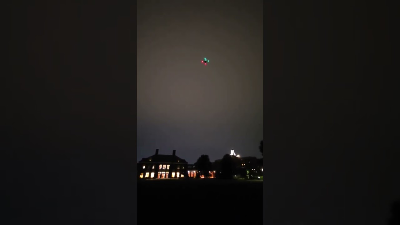
Click to watch: Night flight test captured on my phone. You can hear the motors spin up, see the ROS 2 script execute, and then watch the communication loss unfold in real time.
Nobody was hurt and the airframe damage was repairable, but the experience changed how I approached the rest of the project. We traced the root cause to a telemetry radio interference issue at the specific test location, and after that I implemented three changes: a stricter pre-flight communication link check with minimum signal strength thresholds, a shorter failsafe RTL (return-to-launch) timeout so the Cube Orange would react faster to heartbeat loss, and a mandatory minimum altitude of 5 meters before any scripted waypoint commands could execute. Those changes made every subsequent flight safer.
The other test videos from our successful daytime flights are on a teammate’s machine and I haven’t been able to recover them. But this one tells a more honest story anyway. The successful flights proved the system worked. The crash proved I could diagnose failure modes, implement fixes under pressure, and make the system more robust because of it.
Results
| Milestone | Status |
|---|---|
| First team to achieve stable flight on this platform | Achieved |
| Built complete ROS 2 stack from zero (no prior support) | Achieved |
| URDF model derived from mechanical specs and SolidWorks analysis | Achieved |
| Sim-to-real with same codebase | Achieved |
| MAVROS takeoff, hover, waypoint, land | Achieved (sim + real) |
| ArUco detection and 6DOF pose estimation | Achieved |
| Gazebo Fortress + ArduPilot SITL integration | Achieved |
| Tested in daylight and nighttime conditions | Achieved |
| Crash root cause identified, failsafes improved | Achieved |
| FAA Part 107 compliance for all flights | Maintained |
Team
I led this project and served as Remote PIC for all flights. The team included Sameer Khan, James Kaluna, Xinhao Chen, and Lavinia Kong. Our faculty advisor was Professor Simon Leonard at LCSR.
Links
Code Files
MAVROS Takeoff Service
#!/usr/bin/env python3
# Seyi R. Afolayan - Aurelia X4 Flight Services
# Arms vehicle, switches to GUIDED, commands takeoff to
# specified altitude via MAVROS service calls

import rclpy
from rclpy.node import Node
from mavros_msgs.srv import CommandBool, SetMode, CommandTOL

class TakeoffService(Node):
    def __init__(self):
        super().__init__('takeoff_service')
        self.declare_parameter('alt', 10.0)
        self.alt = self.get_parameter('alt') \
                   .get_parameter_value().double_value

        # Service clients
        self.arm_client = self.create_client(
            CommandBool, '/mavros/cmd/arming')
        self.mode_client = self.create_client(
            SetMode, '/mavros/set_mode')
        self.takeoff_client = self.create_client(
            CommandTOL, '/mavros/cmd/takeoff')

    async def execute(self):
        # 1. Switch to GUIDED mode
        mode_req = SetMode.Request()
        mode_req.custom_mode = 'GUIDED'
        await self.mode_client.call_async(mode_req)
        self.get_logger().info('Mode: GUIDED')

        # 2. Arm motors
        arm_req = CommandBool.Request()
        arm_req.value = True
        await self.arm_client.call_async(arm_req)
        self.get_logger().info('Motors armed')

        # 3. Takeoff to target altitude
        takeoff_req = CommandTOL.Request()
        takeoff_req.altitude = self.alt
        await self.takeoff_client.call_async(takeoff_req)
        self.get_logger().info(
            f'Takeoff to {self.alt}m commanded')
ArUco Precision Landing Detector
#!/usr/bin/env python3
# ArUco marker detection and 6DOF pose estimation
# for vision-based precision landing

import cv2
import numpy as np
import rclpy
from rclpy.node import Node
from sensor_msgs.msg import Image, CameraInfo
from geometry_msgs.msg import PoseStamped
from cv_bridge import CvBridge

class ArucoDetector(Node):
    def __init__(self):
        super().__init__('aruco_detector')
        self.bridge = CvBridge()
        self.aruco_dict = cv2.aruco.getPredefinedDictionary(
            cv2.aruco.DICT_4X4_50)
        self.parameters = cv2.aruco.DetectorParameters()
        self.detector = cv2.aruco.ArucoDetector(
            self.aruco_dict, self.parameters)

        # Load camera intrinsics from calibration
        self.camera_matrix = None
        self.dist_coeffs = None

        self.create_subscription(
            Image, '/camera/image_raw',
            self.image_callback, 10)
        self.create_subscription(
            CameraInfo, '/camera/camera_info',
            self.caminfo_callback, 10)
        self.pose_pub = self.create_publisher(
            PoseStamped, '/aruco/pose', 10)

    def image_callback(self, msg):
        frame = self.bridge.imgmsg_to_cv2(msg, 'bgr8')
        corners, ids, _ = self.detector.detectMarkers(
            frame)

        if ids is not None and self.camera_matrix \
                                          is not None:
            rvecs, tvecs, _ = cv2.aruco.estimatePoseSingleMarkers(
                corners, 0.15,  # marker size in meters
                self.camera_matrix, self.dist_coeffs)

            # Publish 6DOF pose of first detected marker
            pose_msg = PoseStamped()
            pose_msg.header = msg.header
            pose_msg.pose.position.x = tvecs[0][0][0]
            pose_msg.pose.position.y = tvecs[0][0][1]
            pose_msg.pose.position.z = tvecs[0][0][2]
            self.pose_pub.publish(pose_msg)
Gazebo SITL Launch Configuration
# Unified launch file for sim and real hardware
# Brings up Gazebo, ArduPilot SITL, MAVROS, and
# optionally RViz in a single command

from launch import LaunchDescription
from launch.actions import (DeclareLaunchArgument,
    IncludeLaunchDescription, ExecuteProcess)
from launch.conditions import IfCondition
from launch.substitutions import LaunchConfiguration
from launch_ros.actions import Node

def generate_launch_description():
    use_sim = LaunchConfiguration('use_sim')
    use_real = LaunchConfiguration('use_real')

    return LaunchDescription([
        DeclareLaunchArgument(
            'use_sim', default_value='true'),
        DeclareLaunchArgument(
            'use_real', default_value='false'),

        # Gazebo Fortress with Aurelia X4 model
        IncludeLaunchDescription(
            'x4_gazebo/x4_world.launch.py',
            condition=IfCondition(use_sim)),

        # ArduPilot SITL (sim only)
        ExecuteProcess(
            cmd=['sim_vehicle.py', '-v', 'copter',
                 '--model', 'gazebo-iris',
                 '--console'],
            condition=IfCondition(use_sim)),

        # MAVROS bridge (both sim and real)
        Node(
            package='mavros',
            executable='mavros_node',
            parameters=[{
                'fcu_url': 'udp://:14550@',
                'gcs_url': '',
                'system_id': 1,
                'component_id': 1,
            }]),
    ])